 |
|||||||||||||||
 |
 |
|||
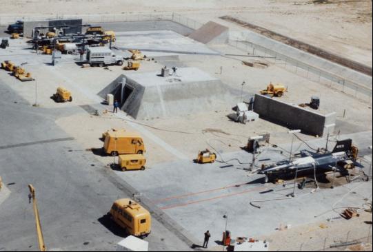
Aerial view of the Propulsion System Test Facility (PSTF), soon after it was built. Armstrong Flight Research Center |
Closer view of the PSTF on 05 Feb. 1959, with the western test stand and blockhouse. North American Aviation |
|||
 |
||
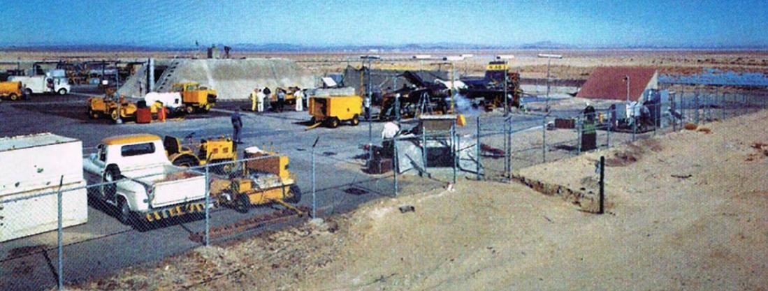
View from outside the PSTF fence, an X-15 is poised for an engine run test in the western PSTS. TD Barnes collection |
||
 |
 |
|||
X-15 no. 3 is locked down and ready for an engine run. Armstrong Flight Research Center |
The LR99 is running at full power as shown by the spacing of the Mach diamonds. Armstrong Flight Research Center |
|||
 |
 |
|||
Two views of X-15 no. 1 in the PSTS on 19 Sep. 1963. The aircraft is being prepared for the first flight by Joe Engle, which will take place on 7 October. Armstrong Flight Research Center |
||
 |
 |
|||
The X-15 is fueled-up and the pilot is in the cockpit, ready for a static test firing. TD Barnes collection |
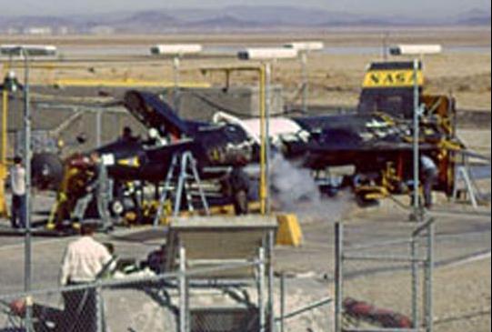
View of the PSTF with two X-15s locked down in their respective test stands. TD Barnes collection |
|||
 |
 |
|||
Locking down the Propulsion System Test Article, connected to the double-stack XLR11-RM-13 rocket engines, prior to a test run. author's collection |
Fireman Jerry Miller moves a fire hose before an engine test. Note that the test article is fueled and ready to run by the vapor coming off the tank at right. author's collection |
|||
 |
 |
|||
Climbing around on the aircraft to make sure all is well before an engine run. Armstrong Flight Research Center |
||||
 |
||||
An evening test stand engine run with the double-stack XLR11-RM-13. Armstrong Flight Research Center |
Fireman Miller at the blockhouse periscope, keeping an eye on the X-15. North American Aviation |
|||
 |
 |
|||
X-15 no. 1 is ready for an engine test early in the rocket plane program. North American Aviation |
The Propulsion System Test Article is connected to the double-stack LR-11s for a test. North American Aviation |
|||
 |
 |
|||
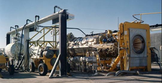
Two views of preparations for a Reaction Motors XLR99-RM-1 test firing, with the rocket engine connected to the Propulsion System Test Article (PSTA). Armstrong Flight Research Center (left) and authour's collection (right) |
||
— Rocket Engine Malfunctions at the PSTF — |
||
 |
 |
|||
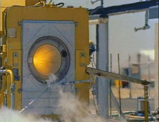
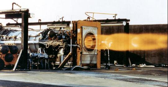
A perfect XLR-99-RM-1 engine run. Note the glowing hot exhaust chamber. Armstrong Flight Research Center |
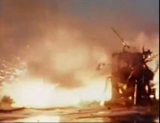
A not-so-perfect engine run on 8 Jun. 1960 resulted in the explosion of X-15 no. 3. NASA Headquarters |
|||
 |
||
A fuel line malfunction, not a problem with the LR-99 engine itself, led to this catastrophic scene where the rear third of X-15 no. 3 was destroyed on 8 Jun. 1960. North American Aviation |
||
 |
 |
|||
Another view of the destroyed aircraft after the engine run explosion. North American Aviation |
The forward fuselage remains of X-15 no. 3 is hoisted away from the damaged PSTS. North American Aviation |
|||
 |
 |
|||
A series of four photographs (above and below) of an engine malfunction that resulted in an explosion in a Propulsion System Test Stand (PSTS). The incident occured on 17 Nov. 1962 and the LR-99 was hooked up to the PSTA (Propulsion System Test Article) rather than an X-15. Armstrong Flight Research Center |
||
 |
 |
|||
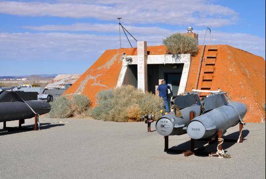
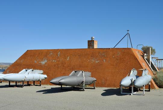
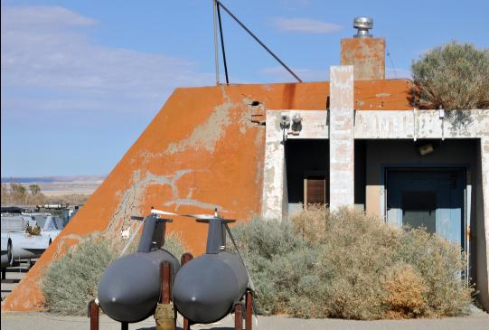
— Propulsion System Test Facility, Post X-15 — photos by Michelle Evans, taken on 12 March 2014 |
||
 |
 |
|||
Exterior of the Control Room Blockhouse (four images above and below). The PSTF is now being used as a storage yard, and also tends to gather a lot of tumbleweeds. |
||
 |
 |
|||
 |
 |
|||
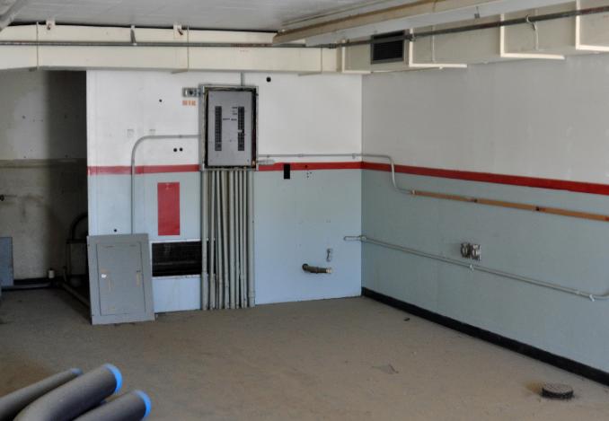
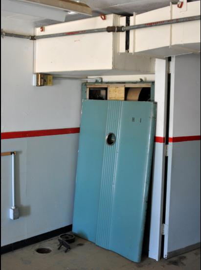
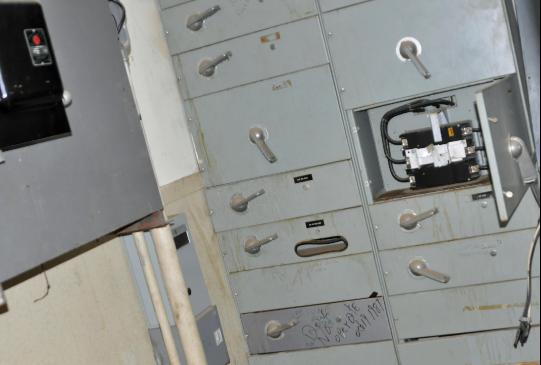
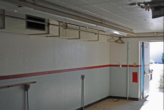
Inside the abandoned blockhouse. This area housed the controls and monitors for the rocket engine tests, while providing protection for the firing crew and observers. All equipment has been removed. Note in the image at below right that an area of the ceiling has been damaged. This is where the periscope was originally located so that an observer could view the engine run directly, as shown in the photo earlier on this page with Fireman Miller. Interestingly, there are also some wire coat hangers hanging from a pipe by the doorway. |
||||
 |
 |
|||
 |
 |
 |
||||
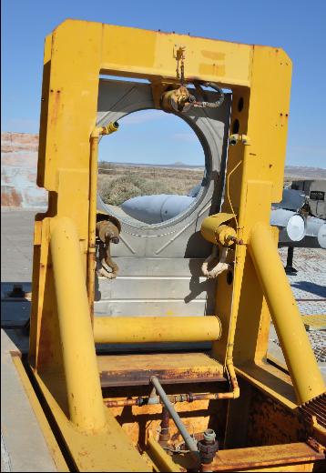
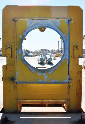
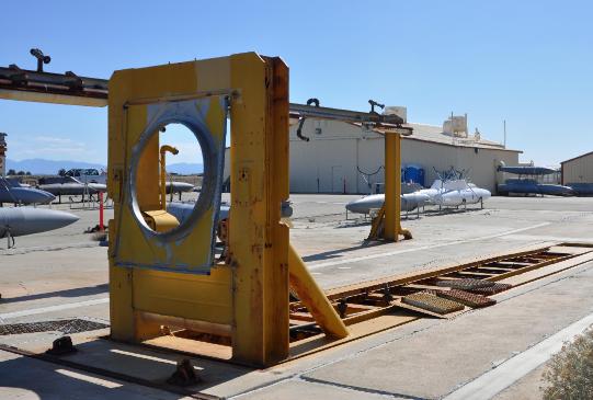
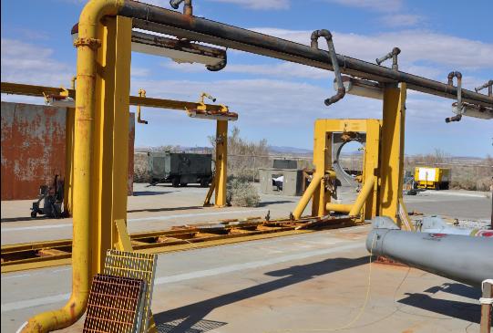
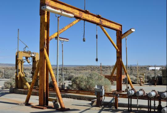
The Propuslion System Test Stand (PSTS) on the east side of the Propulsion System Test Facility (PSTF). The X-15 was backed into the stand so that the rocket engine would butt up against the ring shown above, then locked down. The exhaust would then freely pass through the ring during the test, with the X-15 secured so that it would stay in place even with nearly 60,000 pounds of thrust trying to propel it forward. |
||
 |
 |
 |
||||
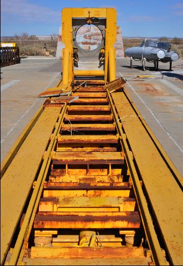
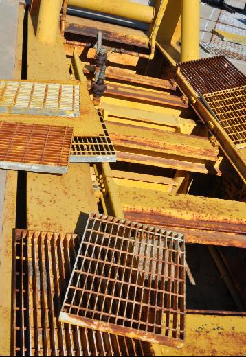
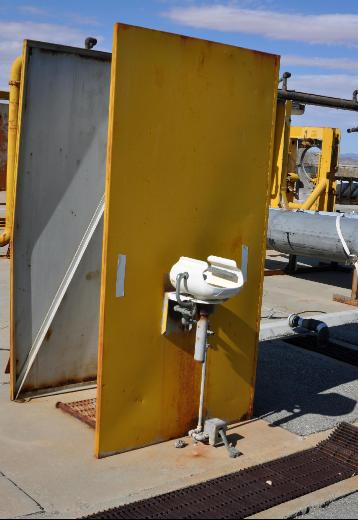
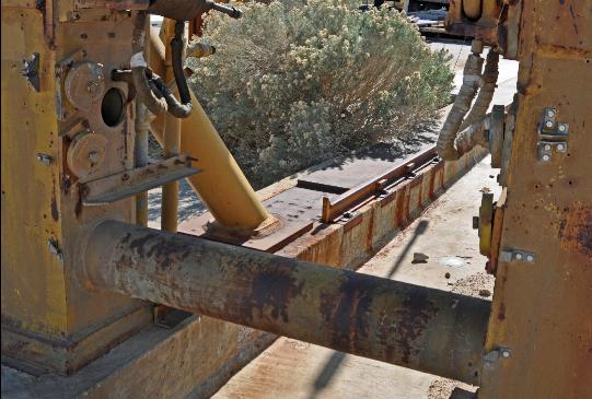
At left is the western PSTS. The center image shows the trench under the eastern stand that ran under the X-15 when it was mounted to the PSTS. This allowed access to all aspects of the aircraft, and is similar to what mechanics sometimes use when working underneath on a car. Note that the protective grating is pulled up. An abandoned eye wash station is seen at right, in case of toxic chemical exposure, a definite hazard when working around rocket engines. |
||
 |
 |
|||
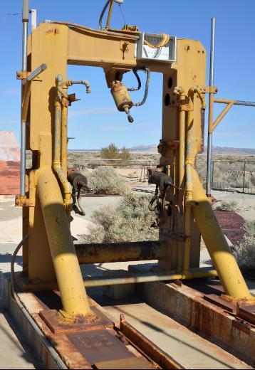
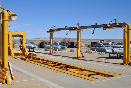
Two photos showing different angles on the eastern test stand. |
||
 |
 |
|||
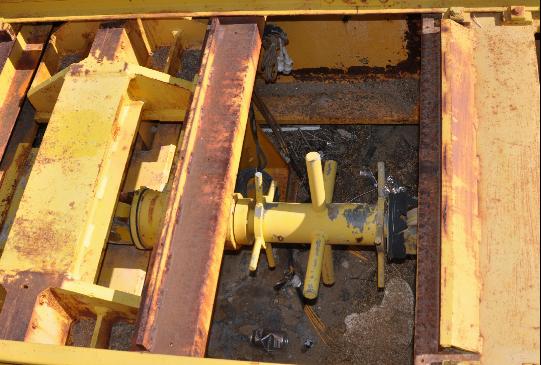
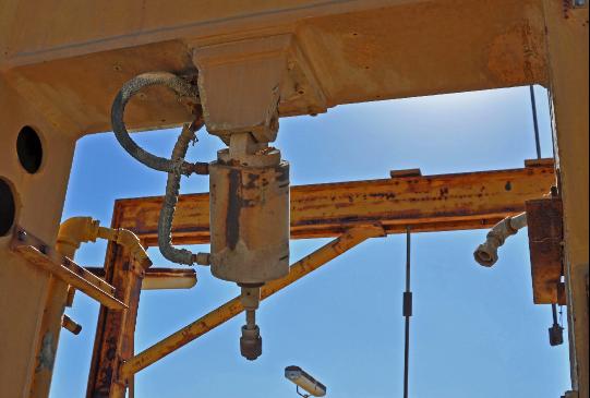
Part of the holding fixture used to precisely place the X-15 into test position. |
The lower two shock absorbers. |
|||
 |
 |
|||
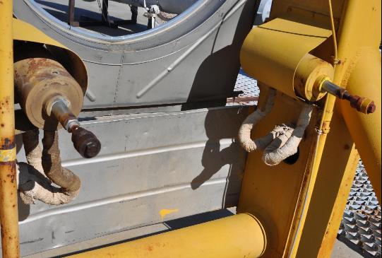
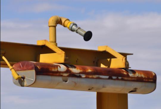
The fire suppression system ran along both sides of the X-15. In the right image is a close-up of one of the water nozzles. |
||
 |
 |
|||
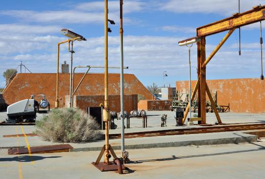
Part of the western PSTS with the central blockhouse/control room also visible. |
Close-up on the massive hold-down fixture at the western test stand. |
|||
 |
 |
|||
An overhead fixture at the western test stand, where cabling can be attached. |
The upper shock absorber at the wesatern PSTS. |
|||
 |
 |
|||
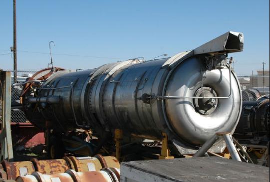
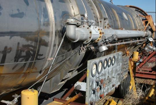
The Propulsion System Test Article (PSTA) is basically a skinless X-15 consisting of the fuel and oxydizer tanks, and all associated plumbing. This would then be connected to an engine in order to do a test firing. The PSTA is now in the Edwards storage yard where it hopefully may be restored one day and put on display at the new Flight Test Museum. |
||
 |
 |
|||
The PSTA in operation during the X-15 program, connected to an LR-99 rocket engine for static fire test runs. Armstrong Flight Research Center |
||