 |
|||||||||||||||
 |
 |
|||
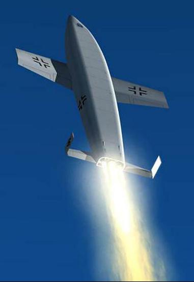
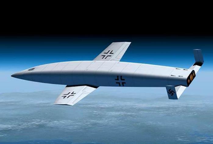
The Eugene Sanger and Irene Bredt concept for an antipodal bomber, also known as the "Silverbird." The idea was developed in Germany as a way for a suborbital vehicle to skip along the upper reaches of the atmosphere to cover intercontinental distances. In this case the design was to be used to bomb New York City from Germany during World War II. After the war, these plans instigated the idea among American aeronautical experts, which led to the eventual development of the X-15 hypersonic research aircraft. author's collection |
||||
 |
 |
|||
The Soviet Union's answer to the American X-plane program was the Samolet 346, which was derived from work in Germany. As seen at right, it was the first experimental aircraft to use an under-wing pylon carry, rather than using the bomb bay of a mothership. Intelligence gathered from the Soviets may have been what triggered the idea for use in the X-15, as it was originally to be carried in the bomb bay of the B-36. Al Esquivel collection |
||||
 |
||
North American Aviation's original proposal for the X-15 research aircraft, known internally as NAA Project 240 (above and below). North American Aviation |
||
 |
||||
 |
||||
— Wind Tunnel Testing — all photos this section NASA Langley Research Center |
||
 |
 |
|||
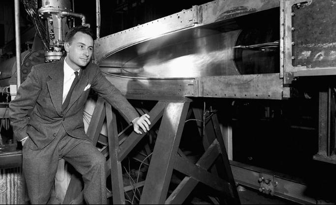
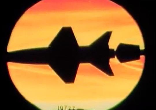
Shock waves off Becker's model at Mach 6.86 and an 18° angle-of-attack, also known as "alpha." |
||||
 |
||||
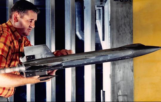
John V. Becker at the Langley Research Center's 11-inch hypersonic wind tunnel on 1 Jan. 1950. |
||||
 |
||||
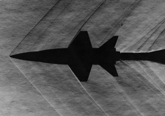
Hypersonic test model top view at 0° alpha and same speed. |
||||
Becker's test model. Note the tiny size for the hypersonic tunnel, and also the 45° cruciform tail surfaces. |
||||
 |
 |
|||
Once the final design of the X-15 took shape, it was back to the wind tunnel for more testing at high Mach numbers. |
||
 |
 |
|||
A technician checks to make sure the model is ready for a test run. |
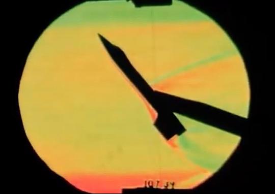
Hypersonic shock waves give visualization to what the X-15 would encounter. |
|||
 |
 |
||||||
 |
|||||||
Larger scale X-15 models prepare for wind tunnel tests. Clockwise from left:
1) A technician positions the speed brakes to study XXtheir effects on the airstream. 2) The X-15 is mounted into the tunnel. 3) A large model is mounted for slow speed tests. 4) Another angle on the model in the wind tunnel XXfrom images 1 and 2. This model appears to be XXapproximately 1/15th scale. |
|||||||
 |
|||||||
 |
 |
|||
Wind tunnel test to check launch of the X-15. Note that the pylon is on the left wing instead of the right, in order to facilitate viewing in the tunnel. The X-15 has just been ejected, and will be captured in the net below the model. Test on 15 Feb. 1958. |
Even after the X-15 was operational, wind tunnel tests continued throughout the program. Seen above is a test of the effects of the X-15A-2 with the external tanks as mounted to the B-52's wing pylon. |
|||
 |
 |
|||
The X-15A-2 being tested in 1967 with the scramjet in place on the lower ventral. |
A delta-wing version of the X-15, also tested in 1967, with a scramjet mounted. |
|||
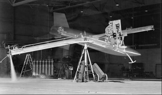
— Helicopter Tests — |
||
 |
 |
|||
A radio-controlled model was developed and dropped from a helicopter in order to test handling characteristics of the X-15 at scale approach and landing speeds. NASA Langley Research Center |
||
— Ballistic Control System Tests — |
||
 |
||||||
 |
||||||
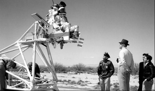
The cruciform Ballistic Control System test rig at Langley on 18 Jan. 1958. Note the X-15 shape superimposed on the open cockpit test rig. NASA Langley Research Center |
||||||
The "right wing" BCS rocket firing, from the now enclosed cockpit test rig. Edwards History Office |
||||||
— The Ejection Seat — |
||
 |
||||
 |
||||
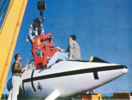
Paul Bikle (left) with Eugene Sanger (middle) check out the X-15 ejection seat. Edwards History Office |
||||
Setting up the rocket sled for a test of the X-15 ejection seat and pressure suit. North American Aviation |
||||
 |
 |
|||
An X-15 foward fuselage section, included space to mount a seat for a full test of the entire ejection system. Here a seat is lowered into the "cockpit" prior to a rocket sled run. The man in the fedora hat is North American Aviation engineer William T. M. "Swampy" Roberts. He earned his nickname as having come from the swamp regions of Mississippi. He was also the designer of the X-15 cockpit. Edward Zadorozny collection |
||||
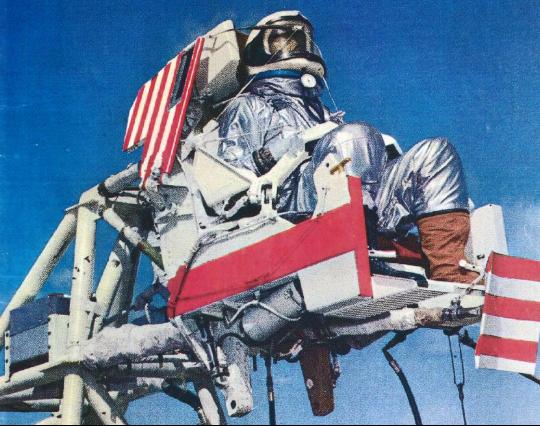
A rare color photo of the bare ejection seat rocket sled test setup. The purpose of this test was to verify the pressure suit's ability to withstand the wind blast of ejection, along with the seat's functionality under similar circumstances. The red-and-white vanes behind the dummy pilot deploy to the side to stabilize the seat after ejection. Edward Zadorozny collection |
||||
 |
 |
|||
Technicians check over the rocket pack at the back of the sled. Soon the cockpit will be closed out, the hatch sealed, and the test initiated. Edward Zadorozny collection |
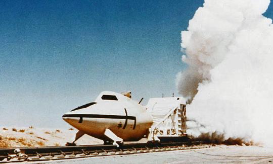
The moment of ignition and the rocket sled is on it's way! Known as the Extended High-Speed Rocket Sled Track at Edwards AFB. The track was 20,000 feet long. Edwards History Office |
|||
 |
||
The ejection sequence unfolds as the rocket sled pushes the test article at hundreds of miles an hour down the track. Clockwise from top left: 1) The sled under full power. 2) The canopy is jettisoned. 3) The ejection seat fires. 4) The seat's stabilizing wings and boom deploy. Edwards History Office |
||
 |
 |
|||
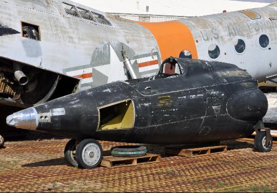
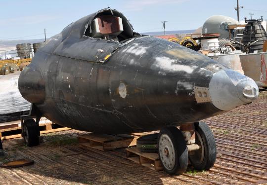
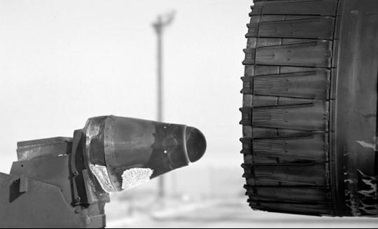
The mockup nose section of the X-15 that was used during the rocket sled tests, sits in the storage yard at Edwards AFB on 12 Mar. 2014. After use on the rocket sled, this was then used as a rescue trainer for personnel who met the X-15 on the lakebed after a research flight landed. Seen behind the mockup is an H-21 Workhorse helicopter, used in X-15 flight operations throughout the hypersonic test program. It is often seen in post landing photos of the X-15. photos by Michelle Evans |
||
— Simulators — |
||
 |
 |
|||
The Q-Ball sensor at the nose of the X-15 would be exposed to the highest heat during flight. In order to test its resilience, the device was hard-mounted in the wake of a jet engine running in full afterburner. Edwards History Office |
Various ways of simulating flight in an X-15 were devised. The most realistic method of simulating approach and landing was to create a simulator that could actually fly. One method of doing this was in an F-100 with a drag chute and speed brakes deployed. Edwards History Office |
|||
 |
 |
|||
Developing the orginal X-15 flight simulator Edwards History Office |
Putting a simulator into a centrifuge to add more realism to the "flights." Edwards History Office |
|||
 |
 |
|||
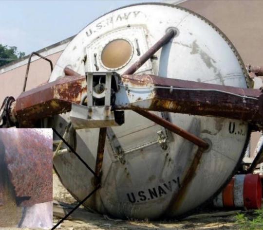
The original centrifuge cabin is now unfortunately rusting away outside in a storage yard, near the building where it used to run X-15 simulations. Eleanor O'Rangers |
||||
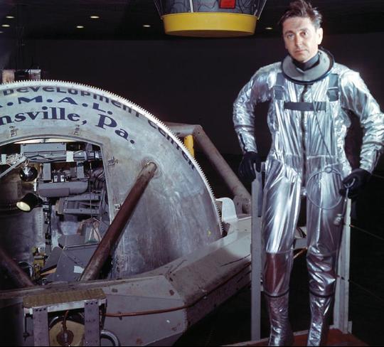
The best simulator was run by the US Navy at Johnsville, Pennsylvania Eleanor O'Rangers and the SE Pennsylvania Cold War Society |
||||
 |
 |
|||
The X-15 "Iron Bird" simulator was developed by North American Aviation. North American Aviation |
The "Iron Bird" in operation at the NAA Los Angeles Division facility. North American Aviation |
|||
— X-15 Completion and Delivery — |
||
 |
 |
|||||
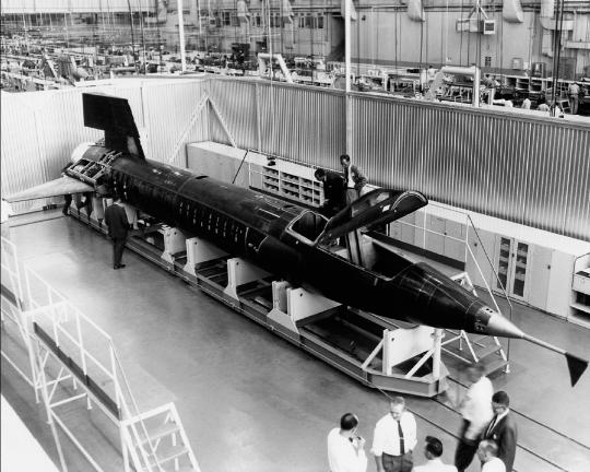
X-15 no. 1 nears completion at the North American plant in Los Angeles. Note the wall built around the aircraft to keep it secret, even from others at NAA. North American Aviation |
||||||
Scott Crossfield in the cockpit of X-15 no. 1 during final assembly. Dr. Toby Freedman, NAA Flight Surgeon stands outside the cockpit, talking to Scott. North American Aviation |
||||||
 |
 |
|||
The X-15 under construction. Gerald Balzer collection |
X-15 no. 1 rolled out on 15 Oct. 1958, then was delivered to Edwards for flight testing. Edwards History Office |
|||